15. Sending events - Part 2

In Part 1, we learned how to send events from C# to Microsoft Flight Simulator using the SimConnect SDK's EventIds. We added two buttons in our WPF app to increase and decrease the barometer setting and resetting it to standard 29.92 with the press of another button. Now let's achieve the same but with a knob connected to the Teensy.
Types of Knobs
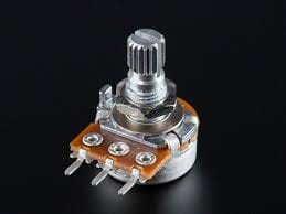
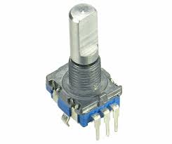
In electronics, two of the most common types of electromechanical rotational input devices are Potentiometers and Rotary Encoders. To the naked eye, they both kinda look the same, but there is a big difference in terms of how they internally work and how to use them. In addition, both them come with an integrated push button which have two additional pins, signal and ground, to determine if the button is open or closed.
Potentiometers

Potentiometers are a three-terminal resistor, that forms as an adjustable voltage divider. You can turn it clockwise and counterclockwise, and they have a minimum and a maximum limit of movement. Two of the pins are connected to ground and a voltage signal, and the 3rd pin is used for the output signal which is proportional to the potentiometer position. Since they have limits, they are typically used for things like volume control, brightness, etc. anything that has a predefined minimum and maximum.
Rotary Encoders

Rotary Encoders are electromechanical devices that convert the angular position or motion of a shaft into digital or analog signals. They don't have a minimum or maximum limit so you can rotate them on either direction infinitely. They also have three pins, one is used for your reference signal (ground or VCC), and the other two are for CLK and DATA signals. These two signals are phased, so depending on the rotation direction, you can determine if its rotating clockwise or counterclockwise based on the values of these two signals combined. That means, the output pattern could look something like (0,0) -> (0,1) -> (1,1) -> (1,0) -> (0,0) when rotating clockwise, and (0,0) -> (1,0) -> (1,1) -> (0,1) -> (0,0) when rotation counterclockwise. They are typically used for adjusting parameters that you just need to infinitely increase and decrease without a limit.
There are even dual rotary encoder versions that have 3 extra pins for an outer ring encoder besides the shaft encoder, which packs much more functionality into a single device, and pretty much acts as if you are working with two independent rotary encoders.
Wiring
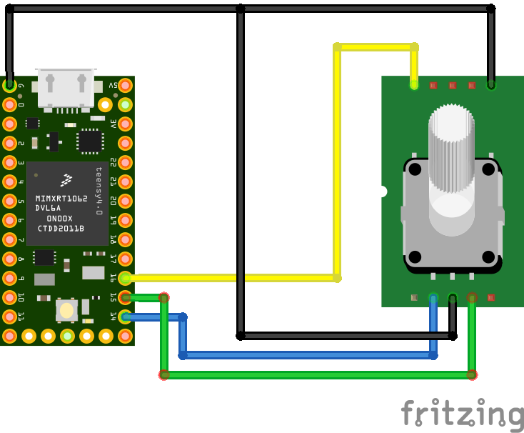
Wiring a rotary encoder can vary depending on what you got. Some come in little development boards with pins that come out so you can connect them on a breadboard, but those boards wire them to Vcc and the logic is inverted. I will be using a standalone encoder like the one in the picture above.
| Teensy PIN | Rotary Encoder PIN | Description |
|---|---|---|
| GND | GND | Ground |
| 14 | CLK | CLK Signal |
| 15 | DATA | DATA Signal |
| 16 | BUTTON | Button Signal |
| GND | BUTTON GND | Button Ground Signal |
The signal pins are arbitrary, so use the ones that are convenient to you.

Implementation
For my instruments, I decided to go with a Rotary Encoder so I can use it to adjust different parameters depending on what instrument I'm building, and if I require min/max limits, it is something I can handle in code. I'm actually using a Dual Rotary Encoder, but the principle is the same.
Let's look at some code:
// set this to the pins you are using on your device. if you notice that the increase/decrease is inverted, swap the CLOCK/DATA PINs
#define CLK_PIN 14
#define DATA_PIN 15
#define BUTTON_PIN 16

int lastEncoderState;

int lastEncoderButtonState;

void setup() {
  // I'm wiring my encoder and buttons to ground, so my signals need to be pullup to use the internal resistance. If you were to wire to Vcc, you probably want to use INPUT instead.
  // this is also a good practice to have your circuit being HIGH at start so you know if you supply enough power to it, vs being low and then doing something that will drain more power than provided.
  pinMode(CLK_PIN, INPUT_PULLUP);
  pinMode(DATA_PIN, INPUT_PULLUP);
  pinMode(BUTTON_PIN, INPUT_PULLUP);

  // store the current state the encoder is when we turn on the arduino
  lastEncoderState = digitalRead(CLK_PIN);

  // open serial connection and wait
  Serial.begin(115200);
  while (!Serial) {}
}

void loop() {
  // read the encoder connected to CLK_PIN, DATA_PIN with last state, and depending on the return value, we determine if we moved clockwise or counterclockwise
  switch (readEncoder(CLK_PIN, DATA_PIN, lastEncoderState)) {
    case -1:
      Serial.println("Encoder Decreased");
      break;
    case 1:
      Serial.println("Encoder Increased");
      break;
  }

  // check if the button was pressed
  if (readButton(BUTTON_PIN, lastEncoderButtonState)) {
    Serial.println("Button Pressed");
  }

  // small delay to give it time for debouncing
  delay(1);
}

// simple funciton that reads the state of a button connected to 'pin', with current and last states for determining if the button is being pressed or not.
bool readButton(uint8_t pin, int& lastState) {
  int state = !digitalRead(pin);

  if (state != lastState) {
    lastState = state;
    if (state == 0) {
      return true;
    }
  }

  return false;
}

// In my encoder, and depends on how you wired it, this is the sequence.
// If yours is inverted, you can invert the CLK and DATA connections
// cw   00,01,11,10,00
// ccw  00,10,11,01,00
int readEncoder(int clkPin, int dataPin, int& lastState) {
  int state = digitalRead(clkPin);

  if (state != lastState) {
    lastState = state;

    int dataState = digitalRead(dataPin);
    if (dataState != state) {
      return -1;
    } else {
      return 1;
    }
  }

  return 0;
}
If we build and run the sketch and open the Serial Monitor window, we can rotate the encoder clockwise, counterclockwise and press the button and see a similar output:

Breakdown
First, we define our pins for CLK/DATA and BUTTON signals. Then we create some variables to store the current and previous states for the encoder and button.
In the setup() function, we set the 3 pins as INPUT_PULLUP since we are connecting the signal to ground. Then we store the last button state so we don't get a false button pressed message.
In our loop() function, we first call readEncoder() to check the state of the encoder. This function returns -1,1 for when the encoder is being decreased or increased, and 0 when it's static. The logic in this function is a bit tricky, but it is based on how our sequence works. Remember that the two signals are out of phase, that means for example, that when CLK is 0, DATA can be 0 or 1 before CLK can change to 1 and so on. This is true only if your reading speed is fast enough, because if you are turning the encoder way too fast, it can jump into the wrong state and you would 'read' movement in the opposite direction, which is something I've even seen on equipment out there... no, I'm not talking about my flight school's $100k RedBird FAA certified simulator that has this issue... nope 🙃
Similar, we call the readButton() function to determine if the button was pressed or released depending on the previous state we stored in lastState.
Note that I made these two functions generic enough so they can be used to verify multiple encoders and buttons, hence I'm passing the lastState argument by reference.Conclusion
That wraps up Part 2 of this series. Now that we know how to use a Rotary Encoder with some pretty straight forward code, in Part 3 we'll apply these changes to the HelloMSFS.ino sketch from Part 1 to send an increase, decrease, and button events to the C# app, so we can then call corresponding SimConnect SDK methods to send that event to the sim.
